How Are Safety Zones Determined in Plants?
A palletizer does not become safe because a yellow line is painted around it. The boundary must account for how fast the machine stops, where a person can reach, what hazards remain after stopping, and how operators actually access the equipment. That is the practical answer to how are safety zones determined: through a documented risk-based engineering process, not by applying a generic clearance distance.
Thank you for reading this post, don't forget to subscribe!In manufacturing and process environments, a safety zone is the controlled area around a hazard where personnel exposure must be prevented, limited, or managed. It may be defined by fixed guarding, perimeter fencing, light curtains, laser scanners, pressure-sensitive mats, interlocked gates, administrative controls, or a combination of these measures. The correct arrangement depends on the machine, process, operating modes, and the level of risk.
How Are Safety Zones Determined? Start With Risk
Safety-zone design begins with a formal machine or process risk assessment. The assessment identifies hazardous energy and situations, estimates risk, and establishes the reduction measures needed to achieve an acceptable level of residual risk. For machinery, this work commonly aligns with ANSI B11 practices, ISO 12100 risk assessment principles, and functional-safety standards such as ISO 13849 or IEC 62061. Process facilities may also need to consider Safety Instrumented Systems under IEC 61511.
The team first defines the equipment’s intended use and its reasonably foreseeable misuse. A guarded robotic cell, for example, must be assessed not only during automatic production but also during manual recovery, teach mode, material replenishment, troubleshooting, cleaning, maintenance, and startup after a fault. Many serious incidents occur during these nonroutine conditions, when normal production safeguards are bypassed or access is required.
Risk estimation evaluates the severity of potential injury, frequency and duration of exposure, and the possibility of avoiding the hazard. A pinch point with infrequent exposure may require a different control strategy than a high-speed robot, a hot process vessel, or equipment with stored pneumatic, hydraulic, electrical, or gravitational energy. The assessment should also identify who may enter the area: trained operators, maintenance personnel, contractors, or visitors.
The Engineering Inputs That Set a Zone Boundary
Once the hazards are understood, engineers establish a boundary that keeps a person from reaching the hazard before the hazardous motion or energy can be brought to a safe state. This is where safety-zone design moves from general policy into calculations, drawings, controls logic, and field verification.
Hazard location and access paths
The first input is the hazard itself. Engineers map moving equipment, crush points, shear points, hot surfaces, energized conductors, chemical exposure points, falling loads, and stored energy. The next question is equally important: how could someone reach that hazard?
A person may approach through an opening in a fence, reach over a guard, step around a conveyor, enter through an interlocked gate, or access a restricted area while clearing a jam. Guard openings, conveyor transfer points, platform elevations, and maintenance access all affect the required zone. A perimeter that protects the front of a machine but leaves access around the side is not an effective safety zone.
Stopping time and safety distance
For presence-sensing safeguarding, the minimum distance between the sensing device and the hazard is driven largely by total stopping time. Total stopping time includes the sensor response, safety PLC or safety relay response, output switching time, brake or valve response, and the machine’s mechanical stop time. A light curtain placed too close to a press, robot, or indexer may detect entry correctly but still fail to stop hazardous motion before a person reaches it.
Safety-distance formulas used in applicable standards translate that timing into a required separation distance. The selected formula and assumptions must match the safeguard type, approach direction, detection capability, and application. A vertical light curtain, horizontal area scanner, and interlocked gate do not use identical assumptions.
Stopping time cannot be treated as a nameplate value. Brake wear, load changes, air pressure, hydraulic condition, motor drive settings, and machine modifications can change real-world performance. A measured stop-time test during commissioning provides a defensible basis for the design. In higher-risk applications, periodic testing should be part of the preventive maintenance plan.
Guard construction and reach-through prevention
Fixed guards and perimeter fencing must be designed so personnel cannot reach the danger area through, under, over, or around the barrier. Mesh opening size, distance from the hazard, guard height, and the geometry of nearby structures all matter. A fence may meet a nominal height requirement yet be compromised by a ladder, pallet, tote, or nearby platform that creates a climb-over path.
The design must also account for ejected parts, sparks, chips, fluids, and broken tooling where those hazards exist. In these cases, the safety zone may require physical containment in addition to access control. A simple perimeter fence is not a substitute for impact-rated guarding or enclosure design.
Operating mode and reset location
Safety zones often change by machine mode. Automatic operation may permit high speed within a fenced cell, while setup or teaching requires reduced speed, hold-to-run control, enabling devices, limited motion, and direct visibility of the hazard area. The controls architecture must make those boundaries enforceable.
Reset devices deserve particular attention. A reset should not automatically restart hazardous equipment, and its location should provide a clear view of the protected area when feasible. If full visibility is not possible, the design may require additional detection, controlled access procedures, or other measures to prevent an unnoticed person from remaining inside the zone.
Safety Zones Need Layers, Not a Single Control
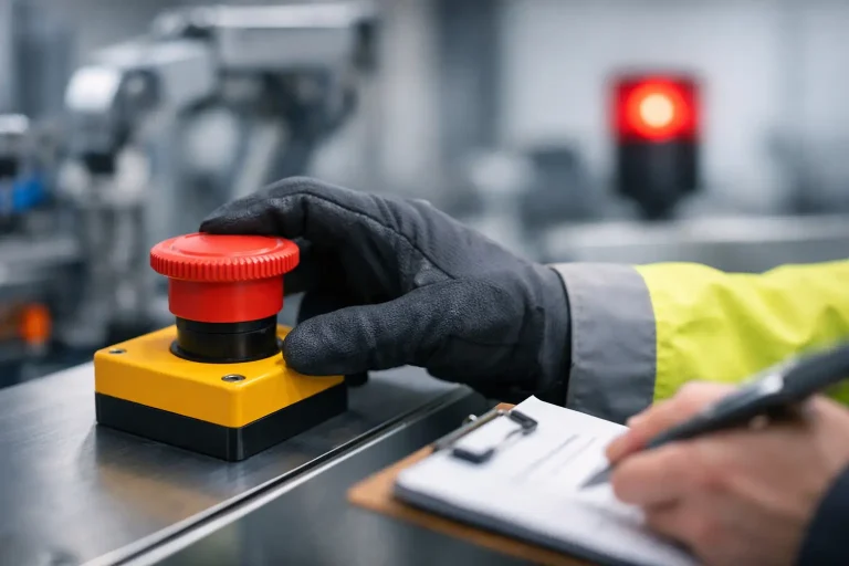
The strongest design uses layers of protection rather than relying on one device to solve every exposure scenario. Fixed guards can prevent routine access, while interlocked gates control entry, light curtains protect material infeed points, and safety-rated monitored stops manage controlled access. Emergency stops provide a supplementary protective measure, but they generally do not replace safeguarding because they depend on someone recognizing the hazard and reacting in time.
A well-designed zone also integrates the safety function into the control system. Safety PLC logic, dual-channel devices, feedback monitoring, safe torque off, safety-rated motion functions, and fault detection should be selected based on the required performance level or SIL target. The safety function must fail to a safe state when a fault is detected within the design assumptions.
This is a common modernization issue. An older line may have fences and emergency stops but lack monitored interlocks, documented stop-time data, or reliable feedback from contactors and valves. Adding sensors without evaluating the full safety function can create a false sense of compliance. The assessment should follow the signal from the field device through the safety controller, outputs, final control elements, and the machine’s actual response.
Validate the Zone in the Field
A safety zone is not complete when the drawing is issued. Validation confirms that the installed system performs as intended and that the residual risk matches the documented design basis. This work should be independent enough to challenge assumptions made during design and programming.
Validation typically includes inspection of guard placement and openings, verification of interlock behavior, stop-time measurement, testing of light curtains and scanners, gate access checks, safety I/O verification, fault testing, and confirmation that reset and restart behavior are correct. It should also confirm that safety devices cannot be easily defeated and that bypasses used for maintenance are controlled, temporary, and visible.
Operational testing matters because plant-floor conditions reveal problems that layouts do not. A gate may be positioned where operators must open it repeatedly to clear normal product variation. A scanner field may nuisance-trip because of forklift traffic. An HMI mode-selection screen may be unclear during recovery. These issues can drive workarounds, and workarounds are often the first sign that a safety-zone design does not fit the process.
Documentation should capture the risk assessment, safety requirements specification, calculations, electrical drawings, safety logic, device data, validation results, and test intervals. When equipment is modified, relocated, sped up, or connected to upstream or downstream automation, the zone should be reviewed again. Changes to throughput or controls can alter stopping time, access patterns, and risk exposure.
Common Design Failures to Avoid
Several failures recur in machine and process safety reviews:
- Using painted floor markings as the primary safeguard around moving equipment.
- Positioning a light curtain or scanner without measured stopping-time data.
- Installing an interlocked gate that can be defeated without detection or control.
- Treating emergency-stop circuits as the only required protective measure.
- Ignoring maintenance, jam-clearing, and manual-recovery access.
- Modifying a line without updating safety drawings, logic, and validation records.
The right answer is not always more fencing or more safety devices. Excessive restrictions can reduce maintainability and encourage bypassing, while an undersized zone leaves people exposed. Effective safety engineering balances protection, production access, diagnostic needs, and lifecycle maintainability without compromising the required risk reduction.
For plant teams, the most useful question is not whether a zone looks adequate from a distance. Ask whether its boundary has been tied to real hazards, measured machine behavior, documented safety functions, and the way people work during every operating mode. That is where a safety zone becomes a dependable control rather than a visual reminder.