How to Optimize PID Loops in Industrial Control
A temperature loop that hunts by 3 degrees, a pressure controller that overshoots after every rate change, or a valve that cycles continuously can become a production problem long before it triggers an alarm. Knowing how to optimize PID loops means treating those symptoms as measurable control-system issues, not simply turning the gain up or down until the trend looks better.
Thank you for reading this post, don't forget to subscribe!PID tuning affects throughput, energy use, product consistency, equipment wear, and operator workload. In continuous and batch processes alike, a poorly tuned loop can conceal mechanical defects, generate nuisance alarms, and make an otherwise capable PLC or DCS appear unreliable. Effective optimization starts with process evidence, then applies tuning changes in a controlled and safe manner.
Start With the Process, Not the PID Constants
A PID controller can only perform as well as the process measurement, final control element, and control strategy allow. Before changing proportional gain, integral time, or derivative action, verify that the loop is operating on valid information.
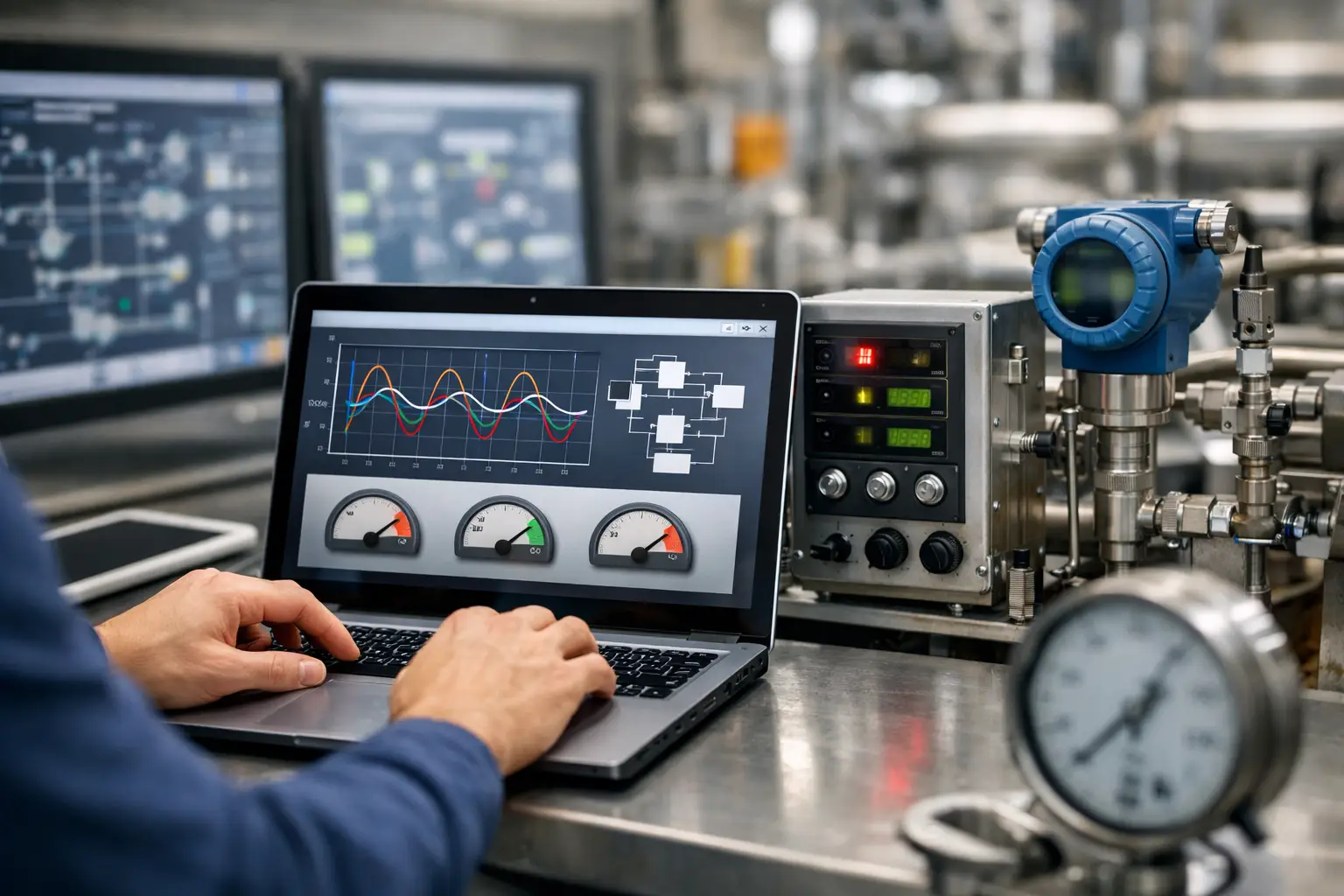
Review the process variable, controller output, setpoint, and operating mode on a common time scale. A useful trend captures normal load changes as well as the disturbance that operators say causes the problem. If the controller output moves but the process variable does not respond, the issue may be a failed actuator, a closed manual valve, a drive limit, or an incorrect control path rather than tuning.
Confirm that the transmitter is calibrated, properly ranged, and installed where it provides a representative measurement. Excessive filtering can add delay and make a stable process appear sluggish. Too little filtering can pass measurement noise directly to the controller, causing output chatter. The correct filter setting depends on process dynamics and required response time, not on a universal default.
The final control element deserves the same level of inspection. Control valve stiction, excessive deadband, improper sizing, poor positioner calibration, and inconsistent pneumatic supply all degrade loop performance. On motor-driven applications, check VFD response, minimum and maximum speed limits, acceleration settings, and feedback scaling. No tuning method can compensate indefinitely for a valve that does not move predictably.
Establish a Baseline Before You Tune
PID optimization should be traceable. Record the current tuning values, controller algorithm, engineering units, output limits, alarm settings, and normal operating range before making changes. A gain value that is appropriate in one PLC platform may behave differently in another because vendors use different PID forms, integral units, derivative filtering, and execution logic.
A baseline should also include measurable performance criteria. For a temperature loop, the target may be reduced overshoot and tighter control within a defined product tolerance. For flow or pressure control, it may be faster disturbance rejection without sustained oscillation. In some processes, minimizing valve travel is as important as reducing error because actuator maintenance and process stability carry real operating costs.
Document whether the loop is direct acting or reverse acting and verify the action with a controlled test. A controller configured with the wrong action can drive the output in the wrong direction when the process deviates from setpoint. This is a basic check, but it remains a common source of commissioning delays and unstable control after system modifications.
How to Optimize PID Loops With Process Testing
The most reliable tuning decisions come from understanding process gain, dead time, and time constant. In practical terms, determine how much the process variable changes after an output change, how long it takes before that change becomes visible, and how quickly the process settles toward a new condition.
For a stable loop, conduct a small, controlled output step while the process is operating in an approved range. Allow sufficient time to observe the response. The step must be large enough to rise above normal process noise but small enough to avoid quality loss, pressure excursions, temperature limits, or production disruption. Where process testing is not acceptable, historical trend data and closed-loop testing methods may provide a safer starting point.
Use the observed response to select conservative initial values. Proportional action provides corrective force, but too much gain produces oscillation and overshoot. Integral action removes sustained offset, but excessive integral action is a frequent cause of slow cycling and windup. Derivative action can improve response in selected applications with measurable rate-of-change value, but it can also amplify noisy measurements. Many industrial loops operate effectively with PI control alone.
Adjust one behavior at a time and observe the result over enough time to account for process delay. If response is slow but stable, a measured increase in proportional gain or a shorter integral time may be justified. If the loop oscillates, reduce gain or slow integral action. If the process reaches setpoint quickly but overshoots after disturbances, reduce aggressiveness and check whether output limits or actuator response are contributing.
Avoid copying values from a similar-looking loop without verifying process characteristics. Two heat exchangers, pump stations, or blending lines can have materially different process gain because of equipment condition, production rate, fluid properties, or valve sizing. Tuning is application-specific engineering.
Address Limits, Modes, and Control Architecture
A loop can be well tuned on paper and still perform poorly because of configuration details around the PID instruction. Output saturation is a common example. When a controller reaches a high or low output limit, integral action can continue accumulating error. Once the process returns to range, the stored integral term can drive a severe overshoot. Anti-windup logic, integral hold, tracking, or bumpless transfer features should be configured and tested where supported by the platform.
Automatic and manual transitions also require attention. Operators need the ability to take control when conditions demand it, but returning a loop from manual to automatic should not create a sudden output bump. Proper output tracking and initialization protect the process and build operator confidence in the automation system.
Check the PID execution interval against process speed. A loop executed too slowly may miss important dynamics. A loop executed much faster than necessary can react to noise and consume controller resources without improving control. In PLC systems, verify task scheduling, scan-time variation, and whether the PID instruction receives a consistent update interval.
Some difficult loops require a control strategy change rather than more aggressive tuning. A jacket temperature loop may benefit from cascade control, with a fast utility-flow loop supporting the slower product-temperature loop. Feedforward can improve rejection when a measurable disturbance, such as production rate or incoming material temperature, affects the process. Split-range control, ratio control, dead-time compensation, and gain scheduling may be appropriate when process behavior changes across operating ranges.
These methods add engineering complexity. They should be selected when the process benefit justifies the additional instrumentation, testing, documentation, and maintenance requirements.
Keep Tuning Changes Inside a Safe Management Process
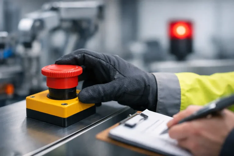
PID changes can affect safety, particularly on processes involving high pressure, elevated temperature, combustible materials, hazardous chemicals, or critical machine motion. The basic process control system should not be treated as a substitute for independent protective layers, safety instrumented functions, emergency shutdown logic, or properly designed machine safeguarding.
Before testing, identify operating limits, alarm response expectations, permissives, interlocks, and any Safety Instrumented System functions that could be affected by process movement. For facilities governed by management-of-change procedures, tuning modifications should be evaluated, approved, documented, and communicated according to the site process. If changes involve safety PLC logic, safety instrumented functions, or SIL/PL-related behavior, they require a higher level of review and validation.
Commissioning should include controlled tests with operations personnel involved. Confirm that alarms remain meaningful, that operator displays show the correct mode and output status, and that data logging captures enough detail to diagnose future performance changes. A tuning change that improves one loop but increases nuisance alarms or trips upstream equipment has not improved plant performance.
Make PID Performance a Maintenance Discipline
A tuned loop is not permanently optimized. Valve friction increases, sensors drift, process loads change, and production teams introduce new recipes or operating targets. Trend-based performance monitoring helps identify control deterioration before it becomes a quality, uptime, or safety event.
Review loops that remain in manual for extended periods, exhibit frequent output saturation, cycle continuously, or generate repeated process alarms. These are useful indicators, but they should lead to root-cause investigation rather than automatic retuning. A controller in manual may reflect an unresolved mechanical problem, an invalid measurement, or an operating procedure that no longer matches process design.
For critical assets, maintain a loop register that identifies service, process limits, tuning parameters, normal operating range, associated alarms, and test history. This supports faster troubleshooting during shifts, strengthens modernization planning, and preserves engineering knowledge when personnel or control platforms change.
The best PID loop is not the fastest one. It is the one that holds the process within required limits, responds predictably to real disturbances, protects equipment, and gives operators a control strategy they can trust.